Thursday, April 26, 2012

120 Track Driver

I have several 120 cc snowmobiles that we use for racing and playing.  These are small childrens machines powered with "lawn mower" type engines.  All of the major manufacturers sell these machines and they are all put together with very similar components.  I have a few older posts about them here, here and here.

These machines use a 12" wide track that is normally driven with involute drivers that engage the track on the rubber "lugs" on the inside of the track.  After a lot of hard use the track and drivers on our Skidoo Mini Z wore out.  In this photo you can see the lugs sticking up on the right side of the track, just outboard of the clips.  The left side of the track is supposed to have lugs also, but they have all been ripped off.  This track is interesting because there is no windows in the track.  The clips are attached to the track with no open holes.


This photo shows a Polaris track with nice tall lugs next to the clips.  You can also see that there is a "window" between each clip.


The track in the Skidoo was obviously junk and the drivers on the drive shaft were pretty worn out.  In the above photo you can see the old drive shaft on the right side (I cut it in half to make it easier to get out of the old bearings.)  As you can see the teeth on the black plastic drivers are rounded off.

The drive shaft on the left side is a Polaris shaft with new "anti ratchet" type drivers.  These drivers are designed to drive the track be engaging the windows on the track and pushing on the clips.  This set has 5 teeth rather than the original 4, this will change our gear ratio quite a bit, making the machine faster on the top end but given up some low end torque.

I ran out of photos, but the new Polaris track and drive shaft fit right into the Skidoo with no problems.

Tuesday, April 17, 2012

CV Boot Replacement Tricks

Modern ATVs use constant velocity (CV) joints on their drive shafts. These joints allow the rotating axles to change direction as the suspension goes up and down or the wheels steer left and right. They serve the same purpose as U joints did on older vehicles. CVs are more complicated and expensive to manufacture than U joints, but they provide a smoother transfer of power and they are normally longer lasting due to the rubber boot that protects the moving parts from water and dirt.  This is the same type of system used on front wheel drive automobiles.

The only maintenance required on them is to inspect the boots and replace them if they are torn or cracked.  Lately I have been replacing a lot of CV boots for people.  I think that the very cold (-30) weather that we had this past winter caused the boot to crack. 


The joints come in two styles, one has a fixed length and the other style can "plunge".  This plunging action allows the length of the axle to change slightly as the vehicle suspension moves.  The upper joint in this photo is a fixed length, the bottom green one is the plunge joint.  Most axles have a fixed length joint on the outboard end and a plunge joint on the inboard end.  

The fixed length joint pulls out of the wheel hub once the large nut on the end is removed.  The plunge joint that goes into the differential is a little trickier to remove.  It is held in place by a little spring clip on the end of the splined shaft.  Too remove the axle from the housing you push the axle all the way in as far as it will plunge, then quickly pull the axle out.  If you do it correctly the axle acts like a slide hammer and it will pop the shaft right out of the differential.


The first step to servicing the CVs is to get the old boots off.  The clamps holding them on come in several different styles.  On some of them it is easy to bend the tabs up to release them, on the stubborn ones I use a cutoff wheel to cut them.  

Once the boots are off you must take the joints apart to clean the old grease and any contamination out.


The above photo shows how a plunge type joint comes apart.  There is a wire snap ring the fits in a groove inside the mouth of the CV cup.  Pop that ring out with a small pick or screw driver and the cup will pull right off.  Once the cup is off there is an external snap ring on the end of the shaft that holds the center of the joint on.


The above photo shows a fixed length joint that has been removed from the shaft.  These are held on the shaft by a spring clip in a groove on the end of the shaft.  When the joint is together there is no access to this clip.  You must force the joint off the shaft over the top of the clip.


Here is the setup that I use to hold the shaft while I pound the joint off.  I have the shaft clamped in a couple of v blocks on the corner of my work bench.  The v blocks are sitting on top of a heavy counter weight from a tractor.  I use this as an anvil, the extra weight makes any pounding that you are going to do much more effective.

Once the axle is secured to something solid I used a large punch and a hammer to drive the center piece of the joint off the end of the shaft.


Carefully lay out the  parts in the order that you take them apart.  It is important to remember which side of each part goes on the shaft first.  The pieces are not quite symmetrical and they will only fit together one way.  Even the small snap ring that goes on the end has a inside and outside face.  Check out this older post for a description of how the snap ring goes and other CV tips.


After cleaning up the parts and inspecting everything it is time to reassemble.  I have been using boots from Moose with good success.  Their standard generic size boot will fit most machines and they also have custom size boots to fit just about any odd size machine.  Since I do a lot of these I purchased their fancy boot clamp tool.  It works a lot better than the free one that come with the replacement boots.  If you have very many to do it is worth it.


Here is the finished axle ready to go back into the machine.


Monday, March 19, 2012

Snowmobile Cylinder Honing


Someone brought me the cylinders from their Polaris 550.  They had burned a piston and one of the cylinders was a little scuffed up.


This engine has traditional aluminum cylinders with cast iron bores.  These are very robust and can take a lot of abuse.  Modern (or high performance) engines have cylinders that are all aluminum with some kind of chrome or Nikasil plating on them.  Plated cylinders allow for greater engine performance (I think it is due to better heat transfer ability), but they don't seem to be as durable when things blow up.  Once the plating starts to flake off the bore you need to have the cylinder replated or replaced.


For this job I am using a cheap "glaze breaker" type tool.  This tool is inexpensive and available at any auto parts store.  It is not a true hone.  It is only used to fixing minor surface defects.  If you have a cylinder that needs to be resized or you need to fix an out of round condition you need a much more complicated and expensive hone like this.

I normally clamp the cylinder to the edge of the work bench and place a pan under it to catch any cutting oil that drips out.


Put the hone in a variable speed drill and insert it into the bore.  Make sure to coat the bore with a light weight oil.  The hone should be spun at a slow speed and moved up and down while it is spinning.


On a properly honed cylinder you want very fine scratches left on the bore.  These scratches hold a little bit of oil and make the rings seat properly.  The scratches should cross each other at about a 30 degree angle.  You have to get the right combination of RPM and up and down movement to achieve this.  Always check the edges of the ports when finished honing.  The edges should have a very slight radius to them.  You do not want a sharp edge that will catch a piston ring when it comes by.  Normally a small piece of emery paper can be used to clean up these edges. 

Friday, March 16, 2012

Arctic Cat Sno Pro 800


Someone brought a new Arctic Cat Sno Pro 800 by the shop recently.  It was only running on one cylinder and needed the spark plugs changed.  I think that they have a habit of warming it up for a very long time before driving it and then hardly getting above idle speed when they do drive it.  This leads to fouled plugs. This machine was built to run fast, not go across town to get groceries.


This second photo show about the best view you can get of the spark plugs.   Like a lot of newer machines this one has part of the chassis structure over the top of the engine.  It may make for a great light weight and stiff chassis, but it sure is a pain to service anything on the engine.  There really isn't a hood to lift up, just two little side covers that give you a peek at the engine.  To make the job a little more time consuming there is 4 plugs for this 2 cylinder engine.

With 4 new plugs in it it ran great.  The power delivery on this machins reminded me of an old 2 stroke moto cross bike from back before they had power valves.  There is a little rumble at low speed and then when you hit the right RPM the thing takes off screaming and stretches your arms out. 

Saturday, March 10, 2012

Rev XP Brake Replacement


For many years almost all snowmobiles were put together in the same way.  It didn't matter what factory it came from , when you opened the hood the pieces were all in the same place.  In recent years there has been a big push to make the machines lighter and more compact.  This has resulted in a lot of changes in the layout and arrangement of the chassis and drive train parts.

The red arrow in the first photo is pointing to the cover over the brake disc on a newer Ski Doo Rev XP machine.  This ones happens to have a 550 fan cooled engine, but all the Rev chassis machines have the brake in this location.  I have seen a few of these get stuck from a build up of snow and ice around the brake rotor.  While riding fine snow can blow in on the hot brake rotor and melt, when you stop for a coffee break it cools off and freezes.  When you try to take off the machine won't move because the brake is frozen in a block of ice.  If you have one of these keep an eye on it.  Make sure you have the correct size Torx wrench in your tool kit to get the cover bolts off.

This particular machine is in the shop to get the brake rotor and caliper replaced.  Someone drove the machine around with the parking brake set and the brake heated up so bad that everything was destroyed.  This is the second time I have seen this happen this year!


Here is the new brake caliper/drive shaft bearing mount.  As part of the effort to save weight and package everything smaller Ski Doo has made the bearing mount part of the brake caliper.  The bearing sits in the large opening, and the four smaller holes bolt the assembly to the side of the tunnel.


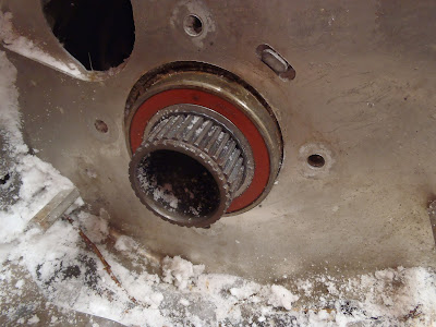
This is the bearing and the end of the drive shaft where it sticks out of the tunnel.  In the old days almost every machine used the same 1" bearings for the drive shaft and the jack shaft.  As you can see in this photo the drive shaft is hollow and uses a large diameter bearing.


Before installing the new bearing mount I heated it up with an electric heat gun.  This causes the metal to expand and increase the size of the hole that the bearing fits in.  On many bearing mounts heating like this can increase the size enough to eliminate any pounding or pressing to install the bearing.


The brake line is connected to the caliper with a banjo bolt.  Make sure you install it with two copper crush washers, one on each side of the fitting.  Once the line is connected the air must be bled out.  See this post for info on how to do that.


Here is the new brake all assembled and waiting for the cover.  Remember if your machine feels a little sluggish make sure you don't have the parking brake set.

Sunday, March 4, 2012

Polaris 120 Snowmobile Rebuild


I have an older Polaris 120 snowmobile that I am rebuilding.  The engine had been neglected, so I decided to tear it down and inspect everything. While I had it apart I also removed the governor.  This is the first step to making these machines run faster.


With no governor to control engine speed the motor will rev up until the valves float.  To increase the RPM that this happens at I decided to install a set of "high performance" springs from Recreational Motorsports.  These springs are little bit longer and stiffer than the stock springs.  After the governor elimination this is the simplest way to make more power. The spring on the right is the new one, the original spring is to the left.


Whenever you are assembling internal engine components be sure to coat all the moving surfaces with some kind of assembly lube.  I normally use Lubriplate.


On these tiny motors I use my simple homemade valve spring tool.  You can see this tool and a manufactured one in these old posts here and here.


These small motors motors have a splash lube oil system.  There is no oil pump to distribute the oil around the engine.  The bottom of the connecting rod cap has a long thin "dipper" that sticks down into the oil reservoir.  As the crank spins this dipper splashes oil up onto the cam shaft and around the crankcase. 


Make sure the timing marks are lined up when the cam shaft is installed.  The small punch marks on the edge of the gears are the timing marks.


This photo shows the main parts of the governor assembly.  The governor can be bypassed by messing around with the springs on the throttle linkage, but this puts a higher load on this plastic gear that will eventually lead to it breaking and making a big mess.  If the governor is not being used it is best to remove this gear.  This photo also shows the governor control rod.  I cut it in half and remove the part that goes inside the crankcase.


When installing the spark coil it must be mounted as close as possible to the flywheel.  I have found that the easiest way to do this is place a piece of paper between the coil and the flywheel when tightening the bolts.  When you turn the flywheel you are left with a paper thin space between the parts.

This covers some of the high lights of small engine rebuilding.  When I get the rest of the machine together I will have more photos of chassis work.

Thursday, February 23, 2012

Ice Auger

I picked up an ice auger from the dump.  It looks like I should be able to get it fixed up without too much work.

I like the names that they give these things.  It is manufactured by "Eskimo" and named the "Barracuda", a tropical fish?  If you look real close you can see that it is Model No. 9000B X.  Do you think that there are 8999 previous models that they made?


Tuesday, February 21, 2012

Outboard Motor Trim Pump


This is the hydraulic trim and tilt unit for a 90 hp Honda outboard.  The unit did not work, so I checked the resistence on the electrical leads and found that it was an open circuit (infinate resistance).  The most likely cause of this is stuck or worn brushes in the motor.  In this photo the motor has been removed and is laying on the work bench, the red stuff is hydraulic fluid where the motor mounts.


When I took the motor apart there was a bit of rust and corossion inside.  The brushes appeared to be OK, but one of the springs had rusted away. 


This motor is built with an internal overheat protection.  It is hard to see with all the rust, but there is two round electrical contacts mounted on a bimetal spring.  If the motor overheats the spring will open the contacts and stop the motor. 


The contacts did not work anymore, so I soldered a jumper wire across them.  There will no longer be an over heat control on the motor, but I think that it is unlikely to be needed in our cold climate.  I reinstalled this part and replaced the spring in the brush holder and the motor runs great now.

Sunday, February 19, 2012

Snowmobile Clutch Removal


I had a Polaris 550 snowmobile in the shop that I needed to pull the clutch off.  This first photo shows the back side of the clutch after the job is all done and it is laying on the work bench.  Sometimes I like to make the first photo something that will look good in the little thumbnail size where this blog is advertised over at the Rudstrom Family Blog.


The first step is to get the correct clutch puller and put some anti-seize on the threads.  There will be tremendous pressure on the threads when it is in use and this will help prevent it from binding up.

They are called clutch pullers, but a clutch pusher would be more accurate.  The tool threads into the clutch body and pushes on the end of the crankshaft.  This forces the clutch off of the tapered end of the crankshaft.


The bolt in the center of the clutch is removed and the puller is threaded in.  On this Polaris machine there is a hole placed in the body for this purpose.


The next trick is figuring out a way to keep the engine from turning over while you screw the puller in.  If you have an impact wrench you can simply buzz it in and the inertia of the engine is enough to keep it from turning.  On some electric start machines you can jam something in the teeth of the ring gear and hold the engine that way.

I have found that the best way to hold the engine is with a piece of rope pushed in through the spark plug hole.  Turn the engine so that it is a little way before top dead center, push a small rope into the cylinder until it is full, then turn the engine so that the piston pushes it against the head.

When doing this make sure that you don't start with the piston too far down in the bore or the rope may go out one of the ports.  If using this technique on a four stroke engine make sure that the piston is on a compression stroke so that the valves are closed.

This method works well on small and large engines.  I once used this idea to hold the crankshaft on the engine in my truck when I was trying to change a timing belt on the side of the road.


You normally have to screw the pull in very tight and when the clutch finally lets go it comes of with a bang.  Here is the end of crankshaft once the clutch has been removed.  The shaft is machined with a slight taper that matches the tapered hole on the clutch.  It always seems amazing to me how all the torque from the engine is transferred by the friction on those two tapered surfaces.

Wednesday, February 15, 2012

Exhaust Spring Tool


Most snowmobile exhaust systems are held together with springs.  The springs allow the the parts to move around with temperature changes and engine movement but always remain in tightly connected.


Removing and installing these springs is easy if you have the right tool.  Here are two spring tools that I made.  One of them is made from an old screwdriver that I ground two notches in the blade.  One is for pulling and the other for pushing.

The second tool is made from the wire handle from a 5 gallon plastic bucket.  The ell shaped bend on the end is originally from where the handle connected to the bucket.  It is just the righ shape to grab the end of a spring.  I put a piece of plastic fuel tubing over the wire to make a softer handle and then bent it into a loop.  This is my favorite spring tool.  It looks crude, but works great.

Monday, February 13, 2012

Yamaha Grizzly Starter


A customer brought in a Yamaha Grizzly that would not start.  When the start button was pressed nothing happened, not even a click from the solenoid.  The battery voltage checked out ok so I tested the power going to the solenoid coil.  A little probing around with a volt meter showed that the solenoid coil was receiving the start signal, but was not working.  The solenoid would have to be replaced. 

After determining that the solenoid was bad I wanted to check out he rest of the system so I jumped the terminals on the solenoid with a screw driver.  This test (which they actually recommend in the Yamaha service manual) can tell you a lot about the condition of the start system.  There are three possible outcomes of this test.  The most common result is no sparks and no starter movement - means that the brushes are worn out or faulty.  The second result is medium sparks and the starter turns - indicates the starter is fine but the solenoid is faulty.  The last result is lots of sparks but no movement on the starter - indicates that the starter is drawing a high amperage but cannot turn.

I found the last result, lots of sparks but no movement.  The next step is to remove the starter and see what is going on.  The plastic body work on the right side needs to be removed and the air intake hose on the clutch cover.  The first photo shows my hand reaching in to loosen the bolts.


Here is the starter sitting on the work bench.  I make a few reference marks on the motor casing before taking it apart.  These marks make it easy to get the end caps back on in the proper order and in the correct rotation.


Here is the starter with the end caps off.  The magnets are broken and the pieces were jammed in tight and preventing the rotor from turning.  I am not sure why the magnets broke.  One possibility is that the faulty solenoid prevented the starter from operating and someone decided to tap on it to get it going.  On a starter with wore out brushes you can sometimes get it to by giving it a few taps to loosen up the stuck brushes.  A few light taps are ok, but maybe someone pounded on it very hard.